
Huzhou jiutong logistics machinery co. LTD
Mobile phone: ms shi 18057236668 / ms CAI 18906723681
Email address: sabrina@jiut.net
Website: www.jiut.net
Address: huzhou and fu town tao jia dun village
Website : en.jiut.net
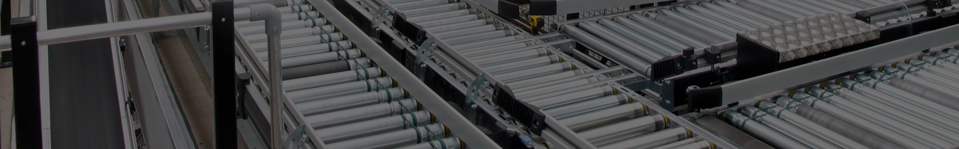
The power roller table is composed of power roller bucket assembly, aluminum side plate, sheet frame, tie rod, bearing seat, drive device and chain. The unpowered roller table is composed of unpowered roller barrel assembly, aluminum side plate, sheet frame, tie rod and bearing seat. The power roller table is driven by the driving device to drive the traction chain, which drives the sprocket wheel on each power roller barrel to rotate, so as to work by rotation. The existing non - power roller conveyor has no special transmission mechanism, low transmission efficiency.
The utility model is mainly solve the technical problems of the existing technology, thus providing a locking piece can be strong support for the first piece of hooking, through the button of the drive roller can be convenient for installation, the roller device can be installed on the unpowered roller conveyor, convenient for auxiliary transmission of unpowered roller conveyor roller device for unpowered roller conveyor.

The above technical problems of the utility model are mainly solved by the following technical solutions:
An unpowered roller conveyor roller device, including support for the first and second support blocks, the first support and the second support blocks of a parallel arrangement, the first to support the outside of the department is equipped with guide block, between the first support and the second support blocks has roller mechanism, guide block is equipped with hooking mechanism, hooking mechanism buckle catches roller; The button-down mechanism includes the support tube, the outer surface of the support tube is covered with a guard tube, the lower end of the support tube is provided with a slide seat, the guide groove and groove are provided on the guide block, and the guide groove and groove are connected, the transverse width of the guide groove is larger than the transverse width of the groove, and the slide seat card is connected in the guide groove; The upper end of the support tube is provided with a lock block, and the outer end of the lock block is fastened on the side part of the roller mechanism.
The upper end of the support tube is provided with a locating tube, a connecting tube is arranged between the locating tube and the upper end of the support tube, and a fixing bolt is arranged between the lock block and the end of the locating tube.
The roller mechanism includes a pair of driving rollers, and a buckle block is arranged between the two ends of the driving roller, and a pair of positioning pipes are arranged at the position of the inward facing surface of the buckle block, and an installation shaft is arranged at the axial position of the driving roller, and the end of the installation shaft is installed in the positioning pipe.
A buckle plate is arranged at the position of the outer side wall of the buckle block, and a fixed rod is arranged between the buckle plate and the outer side wall of the buckle block.
The inner end of the lock block is wider than the outer end.
The roller device for the non-powered roller conveyor which adopts the above technical scheme can be fixed and installed conveniently through the first supporting block and the second supporting block. The roller mechanism can be securely bucked and connected by the bucking mechanism. The fastening mechanism slides along the guide groove and grooves, so as to facilitate the flexible sliding adjustment of the fastening mechanism. The fastening mechanism facilitates the more firm fastening of the roller mechanism. Slide along the guide groove and slotted sliding, which can be convenient to moving regulation of supporting tube, the movement of the supporting tube can control the lock block to realize the mobile body adjustment, through the lock pieces on the first support blocks can be strong jaw, through the button of the drive roller can be convenient for installation, the roller device can be installed on the unpowered roller conveyor, convenient for auxiliary transmission unpowered roller conveyor.


